Thermistor Wiring Diagram
Colors, terminals, functions, voltage path! A line voltage thermostat will typically have wires larger than 18 gauge and may not have terminal labels.
4 Wire Thermostat Wiring Diagram Heat Only For Your Needs
Remove the motherboard of the old 2 wire thermostat and put the new 2 wire thermostat in its place.
Thermistor wiring diagram. If you have a c wire place it into the c terminal on your wall plate. Print the wiring diagram off in addition to use highlighters in order to trace the signal. The diagram shows how the wiring works.
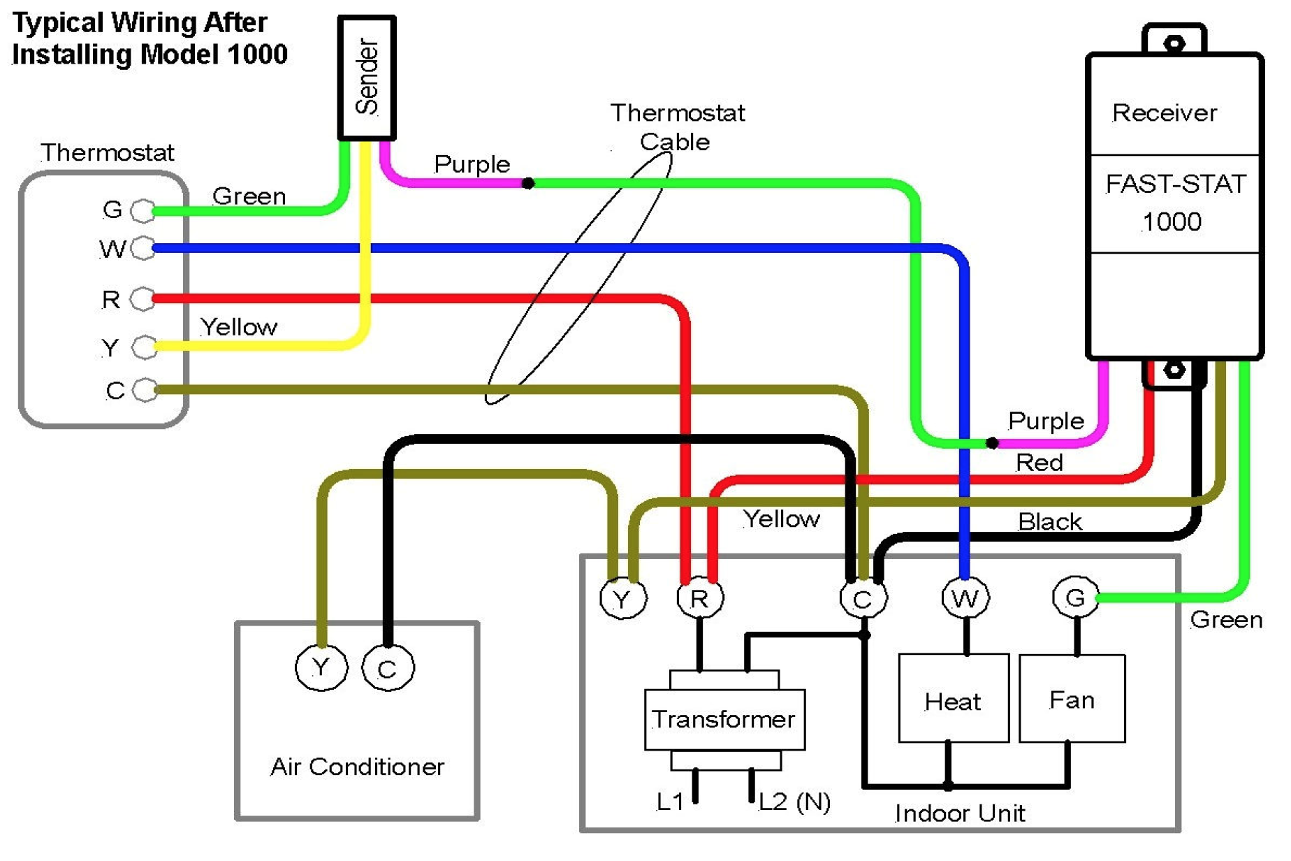
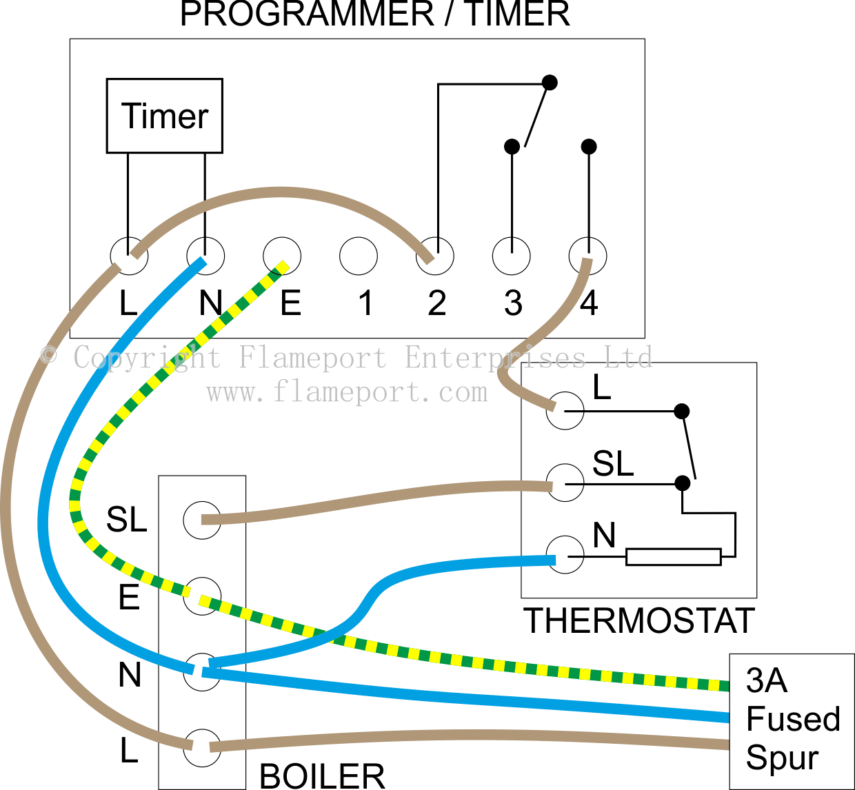
Consult a professional installer for advanced installations, or contact us at 1.844.295.5556 for help. However your connections may seem a little different on the thermostat itself. If your thermostat controls your heat, you will have a white wire.
The y wire is yellow and connects to your air conditioning compressor. For the y y1 and y2 wires y or y1 will go to. This information will be used in step 4 5 to configure your thermostat.
1 heat / 1 cool thermostat. These diagrams depict some commonly used and frequently installed configurations but may not match your hvac system. The color of wire r is usually red and c is black.
The g wire is green and connects to the fan. Thermistor diagram working of thermistor : Thermostat wiring guide | 2 wiring guide thermostat there are no standards for hvac control wiring.
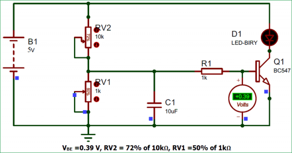
The thermistor is classified into types. The diagram shows how the wiring works. Voltage divider circuit output is connected to the base of npn transistor through a 1k resistor.
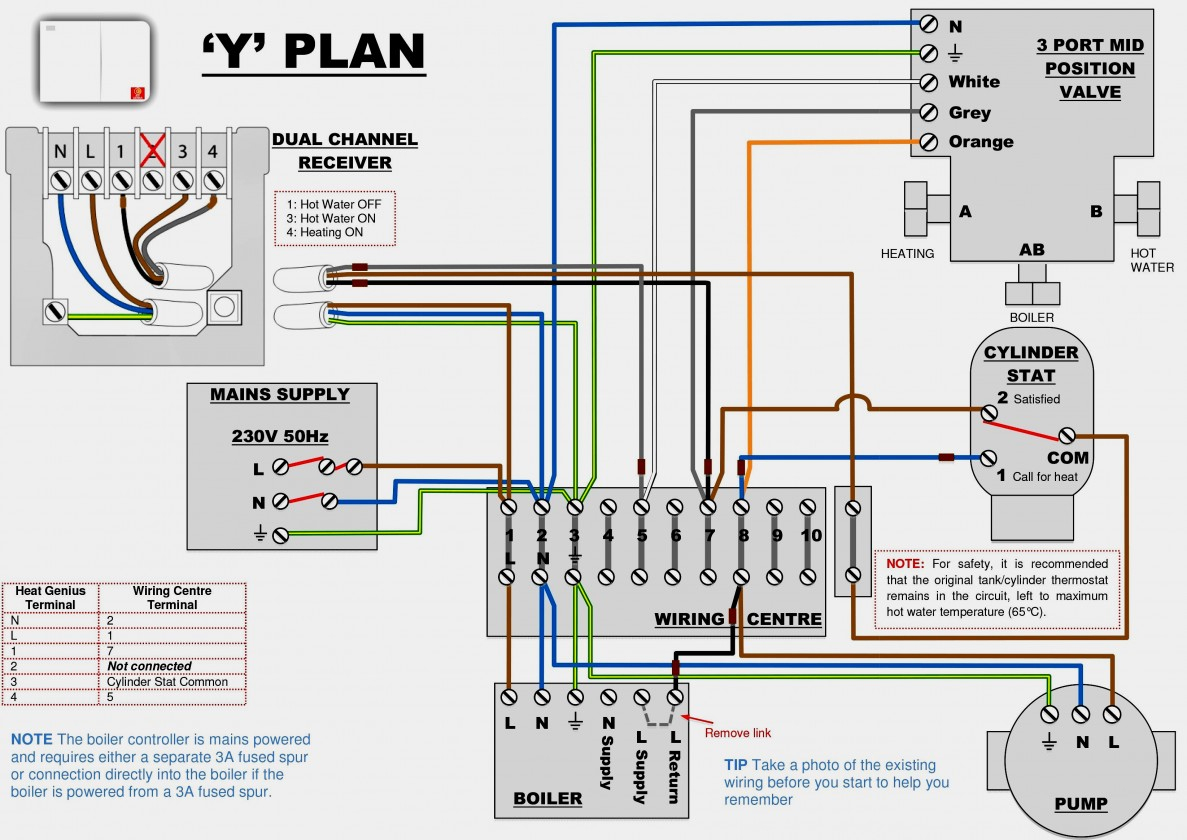
According to earlier the lines in a 2 wire thermostat wiring diagram heat only represents wires. It stands for the physical parts of the electrical circuit as geometric shapes, with the actual power and link connections in between them as thin sides. See the diagram below for what each wire controls on your system:
Wire specifications 18 24 gauge thermostat wire installation notes ensure power at the hvac equipment is off. The variation in the thermistor resistance shows that either conduction or power dissipation occurs in the thermistor. The metal tube, sensing element, and leads together become a thermistor used to measure temperature.
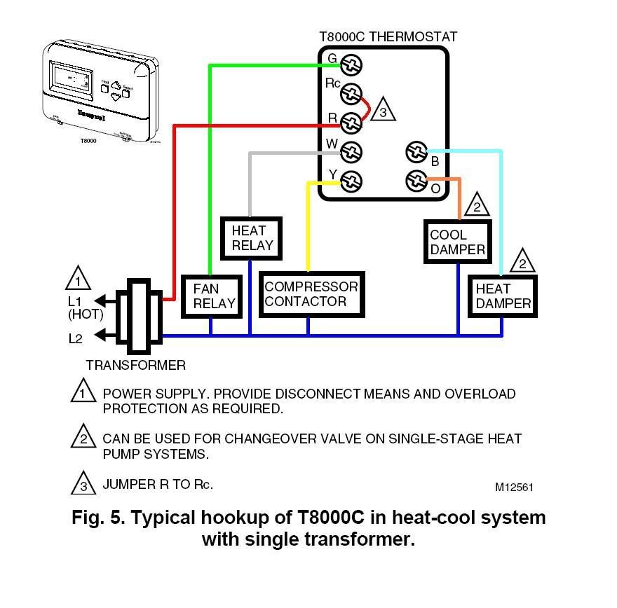
One is for cool and the other is for heat, hence the abbreviation “rh” and “rc”. The circuit compromises of a voltage divider circuit and output “on and off” switching circuit. The nest thermostat is not only the best 2 wire wifi thermostat but it is one of the best wifi thermostats you can get for your home.
It shows the components of the circuit as simplified shapes, and the power and signal friends between the devices. 24v thermostat wiring diagram from 4.bp.blogspot.com. Furnace and ac (color coded) 1 heat / 1 cool thermostat.
3 phase motor thermistor wiring diagram.unless a custom cable is used it seems impractical to screen the power conductors separately from the conductors you would assign to the thermistor wiring. For the y y1 and y2 wires y or y1 will go to. The basic heat + a/c system thermostat typically utilizes only 5 terminals.
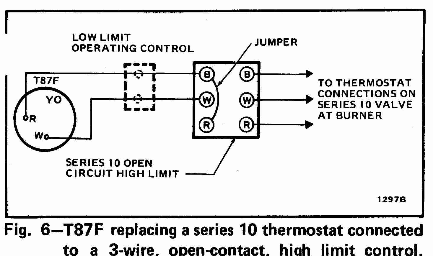
Wire the thermostat diagram 1 model 8344 or 8363 thermostat wiring furnace stage heat 1st stage cool relay cooling equipment cool aprilaire model 8344 or 8363 thermostat elec auto hi opens at 100 f 9 f lo closes at 41 f 9 f. Lead wires are drawn out from the thermistor sensing element as shown in the diagram. The circuit diagram of thermistor uses the rectangular block which has a diagonal line on it.
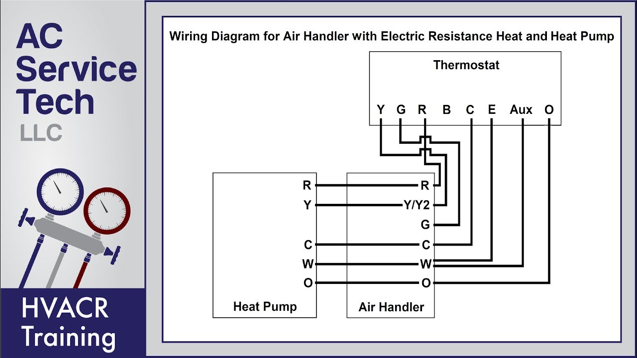
1 heat / 1 cool thermostat. 4 wire honeywell thermostat rth111b wiring diagram. Heat pumps are different than air conditioners because a heat pump uses the process of refrigeration to heat and cool.while an air conditioner uses the process of refrigeration to only cool, the central air conditioner will usually be paired with a gas furnace, an electric furnace, or some other.
These two connections will ensure that there is power to the thermostat that you are operating. Wiring a 2 wire thermostat is pretty straightforward. C is known as the common terminal.
The thermostat uses 1 wire to control each of your hvac system’s primary functions, such as heating, cooling, fan, etc. Heat pump thermostat wiring explained! The leads of the thermistor are connected to a wheat stone bridge as shown in the diagram.
Wiring diagrams heating systems cooling systems lux. At the set point, a temperature rise of a few degrees results in a large increase in resistance. 2 wire thermostat wiring diagram heat only.
The resistance is monitored by a thermistor protection relay (tpr) and, when the sharp change in resistance is detected by the thermistor protection relay (tpr), it operates a contact to initiate an alarm or to trip the protected device. Voltage divider circuit makes it possible to sense the variation in voltage. Thermostat wiring color codes thermostat black or blue wire (“c” wire) thermostat red wire (“r” or “rc” wire) thermostat white wire (“w1” or “w2” wire) orange wire for o and dark blue wire for b (“o/b” wire) thermostat green wire (“g” wire) yellow thermostat wire (“y1” and “y2” wire) other wires (bk, rs1, rs2, odt1, odt2, aux no, aux c, aux nc)
Voltage divider circuit is formed by the thermistor and a variable resistor. 1 trick that i 2. T9 thermostat pdf manual download.
When you use your finger or perhaps follow the circuit with your eyes, it is easy to mistrace the circuit. As shown in the diagram, you will need to power up the thermostat and the 24v ac power is connected to the r and c terminals. If we put it simply, a 2 wire thermostat is one that has only 2 wires coming out of its backside.
In fact the hvac system in your home probably depends on our parts and products to keep it running smoothly. This can be useful for both the individuals and for specialists who’re looking to find out more on.
Honeywell Manual thermostat Wiring Diagram Sample

Residential Thermostat Wiring

Honeywell Ct87n4450 Thermostat Wiring Diagram
Collection Of Heating and Cooling thermostat Wiring Diagram Download

Thermostat Wiring Diagrams! 10 Most Common! YouTube
Get Wiring Diagram for A Nest thermostat Download

Thermostat Wiring Explained

Basic Thermostat Circuit
5 Wire Thermostat Wiring Diagram Wiring Diagram
Thermostat wiring question (HVAC has 7 wires) Ask the Community Wyze Community

Honeywell Thermostat Th9421c1004 Wiring Diagram If You Only Have 2 Wires

Thermostat Wiring Diagram 2 Wire Fantastic Honeywell Thermostat Wiring Diagram 2 Wire

C17 thermostat Wiring Diagram Download Wiring Collection

Honeywell Thermostat Wiring Diagram, Heat Pump Professional Honeywell Thermostat Wiring 3 Wire

I have a 277v line voltage Thermostat that I need to convert to a 24v low voltage system. This

Honeywell Thermostat Wiring Diagram 3 Wire Cadician's Blog
11 Best Typical Thermostat Wiring Diagram Pictures Tone Tastic

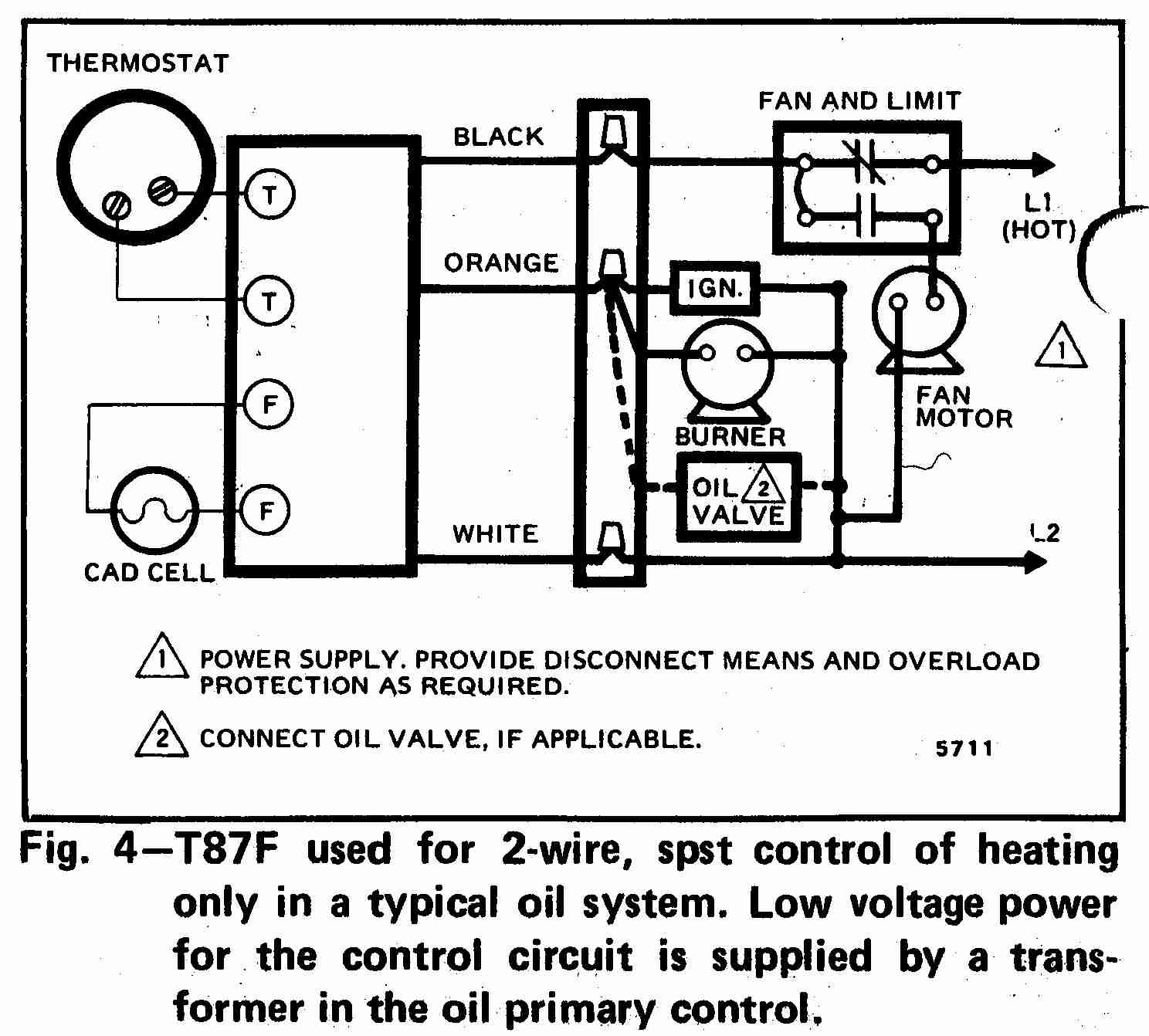
Room thermostat wiring diagrams for HVAC systems
Honeywell Thermostat Wiring Diagram 3 Wire Cadician's Blog